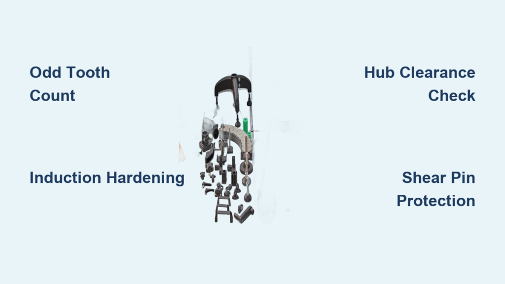
Your industrial conveyor system relies on precise conveyor chain sprocket design to prevent costly downtime and catastrophic failure. Poorly matched teeth cause rapid wear, noise, and chain slippage in harsh environments like cement plants or recycling facilities.
This guide details critical geometry, material selection, and specialized configurations to maximize your system’s lifespan. You will learn how to diagnose wear, select proper heat treatments, and implement safety features like shear pins.
Mastering Critical Geometric Design Parameters
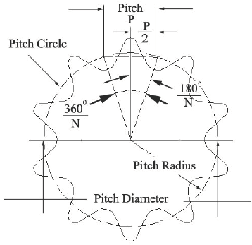
The performance of any conveyor system hinges on exact dimensional control between the chain and sprocket. Minor deviations in critical measurements lead to misalignment, accelerated wear, or complete chain derailment.
Calculating Pitch Circle Diameter Accuracy
The Pitch Circle Diameter (PCD) defines the circle passing through the center of chain pins during engagement. This dimension determines how the chain wraps around the wheel and directly affects meshing quality.
- Use the formula: PCD equals Chain Pitch multiplied by (1 divided by sine of 180 degrees over Number of Teeth).
- Errors in this calculation result in improper tension and increased stress on links.
- Always verify PCD against manufacturer data or ISO standards for your specific chain type.
Optimizing Tooth Count Strategy
Tooth count is not arbitrary and plays a major role in wear distribution. Using an even number of teeth causes the same rollers to engage the same teeth every rotation.
- Select odd tooth counts to distribute contact across more chain links.
- Ensure the small sprocket tooth count does not divide evenly into total chain pitches.
- Avoid divisor relationships to prevent repeated stress cycles on specific links.
Standard configurations include single through quintuple strand sprockets depending on load requirements.
Ensuring Proper Hub Clearance
The hub anchors the sprocket to the drive shaft and must balance strength with clearance. A strict geometric rule applies to all designs to ensure proper function.
Critical Clearance Rule
The hub diameter must never exceed the PCD minus the chain side plate height. If the hub exceeds this limit, the chain rides over the hub instead of engaging the teeth. This “chain lift” causes poor torque transfer and rapid wear on both components.
Bore and Keyway Specifications
Most sprockets arrive bored to size with keyways for secure shaft attachment. Taper lock bushings are widely used for easier maintenance without compromising torque transmission.
- Bore size must match shaft diameter exactly.
- Keyway length should support maximum torque load.
- Double-hub designs offer greater stability in high-torque applications.
Achieving Tooth Profile Precision
The tooth flank is the surface contacting the chain bushing and bears the brunt of friction. High-performance sprockets require CNC-machined teeth for full engagement.
- Flame-cut profiles lack accuracy and produce inconsistent tooth contours.
- Profiles must follow ISO or DIN standards to ensure compatibility.
- Poorly shaped flanks increase noise and accelerate chain wear significantly.
Material Selection and Heat Treatment Protocols
Choosing the right material and applying proper heat treatment is vital for durability. Harsh conditions demand specific engineering solutions to prevent premature failure.
Selecting Base Materials by Application
Different environments require distinct material properties to withstand operational stress.
| Material Type | Best For | Key Properties |
|---|---|---|
| High-Grade Steel | General heavy-duty use | Strong, weldable, cost-effective |
| High Carbon Steel | High wear environments | Hardened surface, good wear resistance |
| Alloy Steel | Shock-prone applications | Toughness, fatigue resistance |
| Heat-Treated Alloy | Drop-forged chains | Case-hardened teeth, ductile core |
Implementing Induction Hardening
Induction hardening selectively hardens only the tooth flanks while leaving the bore and hub soft. This targeted approach is critical for extending component life.
- Hard bores damage shafts due to stress concentration and misalignment.
- Soft bores absorb minor misalignments and protect drive components.
- The process uses high-frequency current to heat tooth tips followed by rapid quenching.
Pro Tip: Always specify induction-hardened tooth flanks for sprockets in abrasive or high-load environments even if the base material is already hardened.
Specialized Sprocket Designs for Demanding Applications

Standard sprockets work for basic systems but advanced applications demand engineered solutions. These designs address specific maintenance and safety challenges.
Split and Segmental Rim Sprockets
These designs are essential for large diameter sprockets requiring crane removal or multi-sprocket shafts. They allow quick replacement in confined spaces without dismantling bearings.
- Constructed from alloy steel with bolted segments and dowel pins.
- CNC-machined tooth profiles ensure full engagement.
- Avoid flame-cut split sprockets as inaccurate teeth lead to poor chain fit.
Shear Pin Sprockets for Overload Protection
A shear pin connects the sprocket to the hub and breaks under sudden overload. This mechanical disconnect happens in milliseconds to prevent chain breakage or motor burnout.
- Electronic overload relays react too slowly to shock loads.
- Shear pins save thousands in chain and motor repairs.
- Replace only the inexpensive pin after tripping to resume operation.
Anti-Clog Self-Cleaning Sprockets
Moist or sticky materials often get trapped between chain rollers and sprocket teeth. This buildup causes accelerated wear and potential jamming in biomass or pulp operations.
- Grooves machined between teeth prevent material buildup.
- The design self-ejects debris during rotation.
- Results include up to 50% longer chain and sprocket life in wet environments.
Drop Forged Chain Sprockets
These are designed specifically for FB-series drop forged chains used in high-torque drag conveyors. They handle breaking strengths up to 67,500 lbs without tooth fracture.
- Multi-piece construction features teeth bolted to a central hub.
- Made from hardened and toughened alloy steel.
- Never pair these with standard roller chain sprockets as designs are incompatible.
Compliance Standards and Dimensional Specifications
No single global standard covers all sprockets but design must align with applicable chain standards. Adherence ensures correct meshing and efficient load transmission.
Key International Standards Reference
| Standard | Application |
|---|---|
| ISO 1977:2006 | General conveyor chains and sprockets |
| ISO 1275:2006 | Double-pitch precision roller chains |
| ISO 6971:2002 | Cranked-link drag chains |
| ISO 6973:1986 | Drop-forged rivetless chains |
| BS 4116-4:1992 | British series chains |
| DIN 8165-1:1992 | FV-type solid bearing pin chains |
Understanding Standard Sprocket Types
Standard classifications help identify hub configurations and strand compatibility.
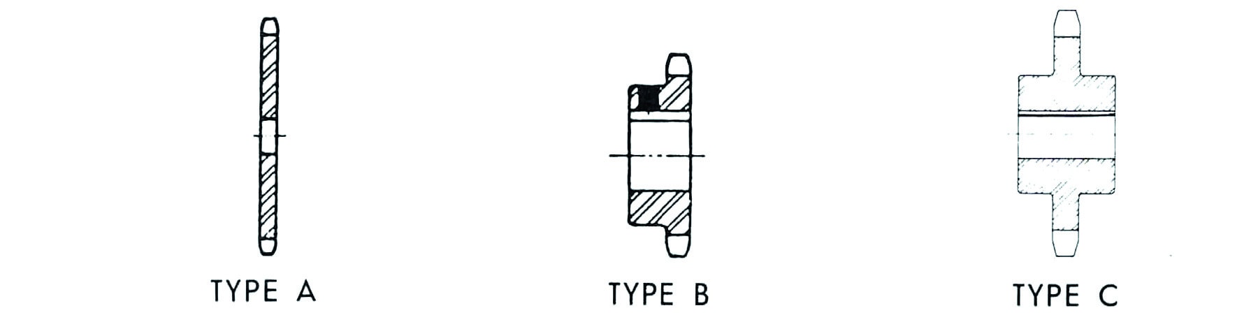
- A Type: Plain hub with no projection.
- B Type: Hub on one side only.
- C Type: Hubs on both sides for stability.
- Triple Type: Three-strand chain compatibility.
Always confirm sprocket dimensions against chain manufacturer specs before ordering. Custom options include non-standard bore sizes, special alloys, and modified PCD.
Wear Diagnosis and Replacement Timing
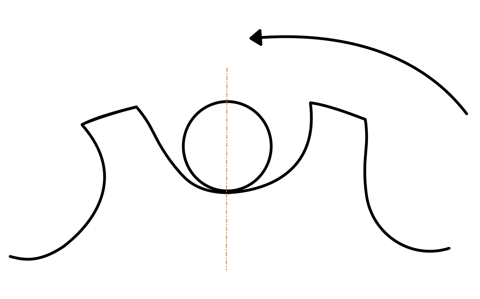
Even the best-designed conveyor chain sprocket wears out over time. Knowing when to replace it is crucial for preventing catastrophic system failure.
Identifying Signs of Sprocket Wear
Visual inspection reveals critical wear patterns that indicate immediate attention is needed. Look for hooked tips bent forward from chain pull or thinned flanks at the engagement point.
- Uneven wear on one side indicates misalignment issues.
- Chain jumping suggests poor meshing due to profile deformation.
- Shine a flashlight along the tooth face to see shadow lines near the tip.
Managing Chain-Sprocket Interaction
Never install a new chain on worn sprockets. The new chain will not seat properly and will wear rapidly due to mismatched geometry.
- Replace chains and sprockets in pairs for maximum life.
- Inspect all sprockets on shared shafts if one shows wear.
- Environmental factors like abrasive dust accelerate flank erosion.
Maintenance Schedule: Inspect sprockets monthly in harsh environments and quarterly in light-duty systems.
Application-Specific Design Guidelines
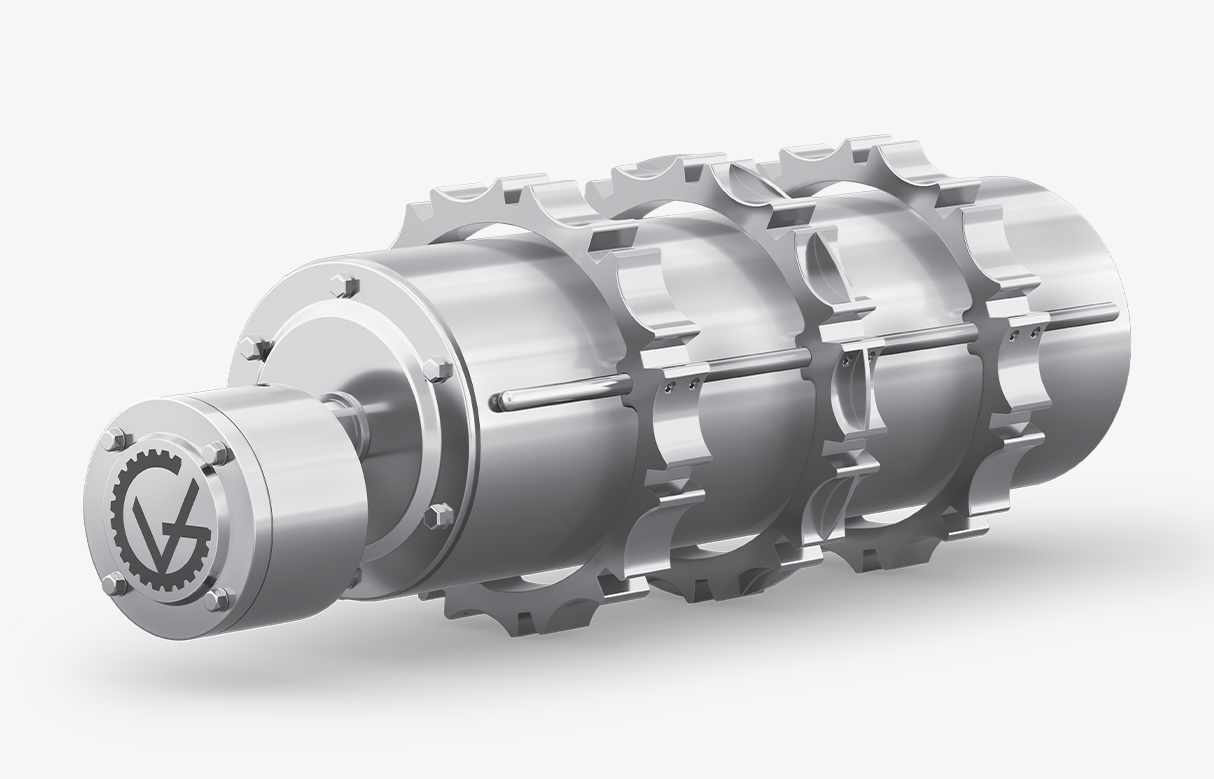
Different industries face unique challenges that require tailored conveyor chain sprocket design solutions.
Drag Conveyor Systems
Drag conveyors run slow but under high tension requiring strength over speed. Drive sprockets transmit power while tail sprockets maintain tension.
- Use split or segmental rims for easy maintenance.
- Specify induction-hardened teeth for long life.
- Include shear pin protection on the drive end.
Pulp Paper and Biomass Operations
These facilities handle wet fibrous materials with continuous operation. Moisture and stickiness create significant clogging risks.
- Install anti-clog sprockets with self-cleaning grooves.
- Use stainless or coated alloys if corrosion is severe.
- Choose odd tooth counts to spread wear evenly.
Cement and Recycling Facilities
Extreme abrasion and heavy impact loads define these environments. Foreign object jams from metal or rock are common occurrences.
- Select high-carbon steel that is hardened and tempered.
- Utilize split sprockets for fast changeouts.
- Combine shear pins with magnetic pre-screening to reduce jams.
Frequently Asked Questions About Conveyor Chain Sprocket Design
Why should I choose an odd number of teeth for my sprocket?
An odd tooth count ensures the engagement pattern shifts with each rotation. This distributes wear more evenly across all teeth and rollers compared to even counts.
What happens if the hub diameter is too large?
If the hub exceeds the PCD minus chain side plate height the chain will ride over the hub. This causes chain lift inefficient power transfer and rapid wear.
When is a shear pin sprocket necessary?
Use shear pin sprockets in systems prone to sudden overloads like recycling or waste processing. They disconnect the drive instantly to prevent motor or chain damage.
Can I install a new chain on my existing sprockets?
No you should never install a new chain on worn sprockets. The mismatch causes improper seating and rapid wear on the new chain components.
How does induction hardening benefit sprocket performance?
Induction hardening hardens only the tooth flanks while keeping the bore soft. This protects the drive shaft from damage while maximizing wear resistance.
What standards govern conveyor sprocket dimensions?
Designs typically follow ISO 1977 ISO 6971 or DIN 8165 standards depending on the chain type. Always verify dimensions against specific manufacturer specs.
Key Takeaways for Optimizing Conveyor Chain Sprocket Design
Effective conveyor chain sprocket design combines precise geometry with smart material choices. Prioritize odd tooth counts induction hardening and proper hub clearance to extend system life.
Implement shear pins for safety and anti-clog features for wet environments. Regular inspection and paired replacement of chains and sprockets prevent costly unplanned downtime.
Evaluate your current system against these best practices today. Upgrading to specialized sprocket designs can significantly reduce your total cost of ownership.